We finished up PopsicleBot StickBot with a couple of 555 timer circuits to allow it to roam freely and untethered. It was a lot of fun to build, and even though it’s not the fastest walker or the simplest design, it feels very organic, partly because it’s entirely analog. (As another reader noted, it would have been a lot easier to just use a Microchip PIC12F683 — or PICAXE-08M or 08M2 — but that wouldn’t have been quite as fun, and I was really looking forward to making “eyes” out of the circuits.) See the original post here: StickBot: A Simple 6-Legged Walker. You can click on any of the photos to see larger versions.

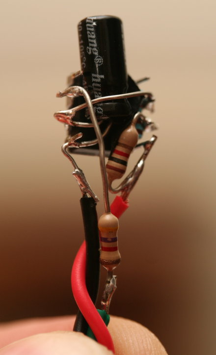
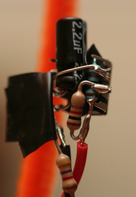
There’s a 9V battery now attached to its belly with a cable tie. The power feeds into a 7805 voltage regulator, which is fastened with a drop of glue and another cable tie under its nose. 5V and GND are fed up to it’s right eye, where a 555 timer is set up to oscillate between 0 and 4.25 volts with a frequency of 1Hz — so a half second for the left step, then a half second for the right, and so on. The green wire is the 1Hz square wave output.

The soldering work is far from beautiful, but it is functional, and of course wrapping it up in tape makes it look a little cleaner. You can see where I slipped in little pieces of electrical tape where needed to avoid unwanted connections. There’s a video of soldering up one of the eyes here: StickBot - Building the Right Eye
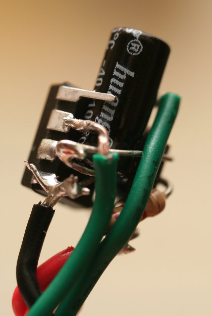
5V and GND are also fed up to the left eye, where the inner green wire carries the 1Hz square wave generated by the right eye, and the outer green wire carries the servo control signal. The 555 circuit that makes up the left eye creates this control signal, using (in part) a resistor (R3) that I bundled with the other eye. I did this to keep the number of components in each eye balanced. Nobody wants to see a PopsicleBot StickBot with one eye that’s much bigger than the other!
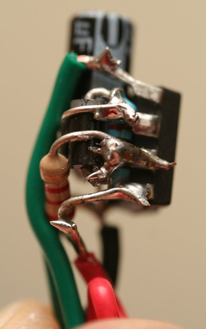
To simplify the soldering work, I left pin 4 (reset) empty on both circuits, as well as pin 5 (the control voltage pin) on the 1Hz oscillator. Ideally, you’d tie both reset pins up to 5V, and tie the empty pin 5 to ground through a 10nF capacitor. This keeps unwanted noise from potentially affecting the circuit.
Here’s the schematic: (Click for a larger version.)

…and here’s the video:
Resources
Here are some helpful resources if you’re working with 555 timer circuits.
- 555 Timer Oscillator Frequency Calculator – Input a frequency, and get back a list of possible resistor and capacitor values.
- Astable 555 Square Wave Calculator – Essentially the opposite of the previous calculator, input the resistor and capacitor values and get back details about the output.
- 555 Control Pin Visualization – This is a good visualization of how the control voltage pin affects the 555.
- Ohm’s Law Calculator – What list is complete without one of these?
- Resistor Color Code Calculator – If you need help with resistor color codes, this site lets you convert both ways — from codes to values or from values to codes.
Updated Name
I realized that Popsicle was actually a registered brand name and not just a common word, so in order to avoid any confusion or trouble, I changed this little guy’s name to StickBot. This project does not (and never did) have anything to do with Popsicle brand ice pops. In fact, I’m not even sure the craft sticks I uses were actually from Popsicle brand ice pops. So my sincere apologies to the Popsicle people; I hope you continue to let me eat your ice pops because life would simply not be the same without them!
[…] goes to the Frankes for the original […]
[…] goes to the Frankes for the original […]
Hi… Hiw do i control the servo speed. I want it to sweep slowly to the left and right with 4 second interval. Tq