
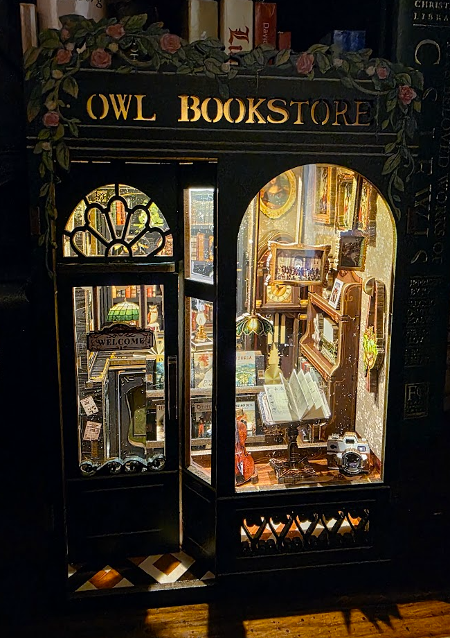
A few months ago I got this cool miniature bookstore diorama “puzzle” from Amazon. It’s charming. Laser-cut wood, tiny bookshelves, warm white LED lighting — the kind of cozy miniature bookstore scene that slides between books on a shelf and makes you feel slightly more literary just by proximity.
The mechanical build was satisfying. The aesthetic result was great. The electronics sucked.
The Problem: “On” Is Not a Feature
The lighting circuit included with this thing is about as simple and unintelligent as it gets:
- Two AAA batteries
- A white LED
- A transistor used as a switch
- A capacitive touch toggle switch
That’s it. No timer, no auto-off, no regard whatsoever for power management. The transistor simply switches battery current directly to the LED, with no limiting. If you forget to turn it off, the batteries go dead pretty quickly.
That annoys me more than it probably should. And because this thing lives in a bookshelf, it’s really easy to forget it’s on. It just silently drains batteries until it doesn’t work anymore. And then I have to walk all the way upstairs, get some new batteries, carefully open the back compartment, replace them, and hope I don’t leave it on again. Too much effort. Hmpf.
The Opportunity: There’s Room Back There
On the back of the diorama is a small battery compartment with enough unused space to fit a small PCB. Not a lot of space, but enough by my estimation. I’m a sucker for spending waaaaay too much time solving stupid problems, so I decided to go for it.
Instead of a dumb LED switch, I want:
- Better touch activation (the current sensor barely worked through the wood)
- Automatic shutoff after a configurable duration
- Microamp-level sleep current
- DIP switch runtime timer delay selection
- Clean low-side LED switching
- Proper current limiting
- And, of course, firmware written from scratch 😉
A real well-engineered embedded device… not because it needs to be, but because it’s there and it’s kinda calling out to me.
Design Goals
Here are my goals:
1. It must fit in the existing battery compartment
No external boxes. No visible mods. Ideally something that looks nice attached to a battery holder.
2. Battery life must dramatically improve
The stock design happily dumps ~10 mA continuously into the LED. If accidentally left on, that’s roughly 240mAh/day, so maybe four days total on fresh batteries.
The new design should:
- Sleep in the single-digit microamp range
- Only draw LED current while intentionally on
- Find a “sweet spot” for current vs brightness
- Shut itself off automatically
3. No external RTC or complex parts
I want to keep this simple and elegant yet still have that “significantly overthought” flair. I admit I’m *really* tempted to slap an ESP8266 in there with ESPHome and connect it to my home automation, but in this case I want to try to keep it even simpler. I have a couple of ATTiny85’s lying around still and the handful of components needed to support this project on that MCU seems like a good fit (literally).
4. Make it configurable
Seems to me we’re going to want to have it on for a configurable period of time. I have some three-position DIPs and a few extra pins, so I’ll allow those to set the default. Maybe later I’ll add some code that overrides this default with things like double-, triple-, and quadruple-taps.
Why an ATtiny85?
Well, first of all, I have some. Also it really does hit the sweet spot for this project:
- Tiny footprint (8-pin DIP or SOIC)
- Internal oscillator
- Watchdog timer
- Pin change interrupts
- Very low power sleep modes
- Cheap
- Well understood
- Widely available
Plus even it is arguably overkill for “turn a light off after 30 minutes” sort-of circuit, so I think that just adds to the charm. haha
The Architecture (High Level)
Here’s the lazy conceptual plan: Sleep, sleep, sleep. Sip electrons ever so slowly. Sleep as deeply and unconsciously as possible until touched. Then wake up, configure, calculate, activate, and then immediately go straight back to sleep for as long as possible. Every time it wakes up, it should prioritize going straight back to sleep.
Key principles:
- Use interrupts, not polling
- Deep sleep in power-down mode
- Use the watchdog timer for coarse timekeeping
- Disable every peripheral that isn’t actively needed
The first milestone is the firmware, because good embedded systems start with behavior, and I like writing code. Then I’ll breadboard it, test it, and design a custom PCB. If I can get it to fit just right (and I feel like that should work just fine) then I’ll even design some sort of 3D printable enclosure to keep things nice and tidy.
The Roadmap for This Series
Here’s how I expect this series will unfold:
- Part 1 – Introduction (this post)
- Part 2 – Writing the Firmware
- Part 3 – Programming the AVR
- Part 4 – Circuit Development
- Part 5 – Integration and Assembly
I’ll release everything Copyleft, too. Hope you enjoy the ride!