Welcome to theFrankes.com!
Welcome to theFrankes.com. This blog has been around for decades now, and I do have a full-time job and family, so please be patient as I get it back up to modern standards. It’s a long, slow process that competes…
Welcome to theFrankes.com. This blog has been around for decades now, and I do have a full-time job and family, so please be patient as I get it back up to modern standards. It’s a long, slow process that competes…
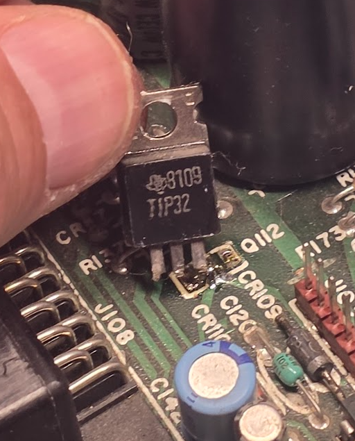
A couple days ago, after putting off the project for decades (you know, kids and all), I finally dug out the old Atari 800 I had as a kid. The 800 fired up after a bit of cleaning but I’m…
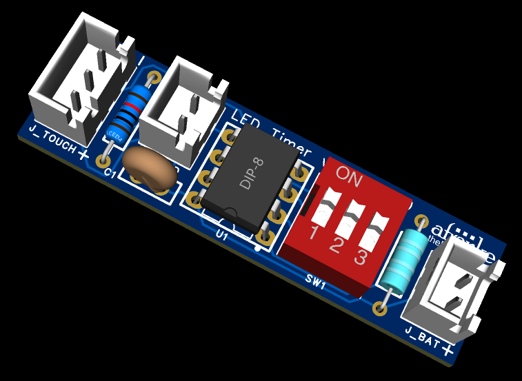
The Circuit: Designing for Low Power, Clean Logic, and Physical Constraints In Part 1, I explained why I tore out the original “transistor-and-hope” lighting circuit from my Book Nook kit.In Part 2, I went through the firmware architecture around watchdog…
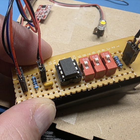
This is Part 2 of the BookNook Light Timer Series. Last time I introduced my BookNook Light Timer project and walked through how I planned to complete it using an ATtiny85 microcontroller. In this post, I wanted to unpack the…
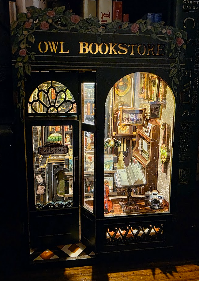
A few months ago I got this cool miniature bookstore diorama “puzzle” from Amazon. It’s charming. Laser-cut wood, tiny bookshelves, warm white LED lighting — the kind of cozy miniature bookstore scene that slides between books on a shelf and…

Planning a trip to Thailand? One of the biggest hidden costs can be how you exchange your dollars for Thai baht. After reviewing my own travel data from past trips and current rates in December 2025, I wanted to share…
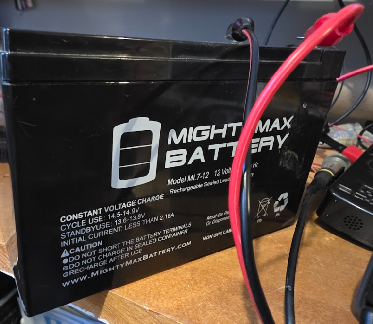
I have this little SLA battery that enables my emergency generator to start without using the pull cord. I don’t have a maintainer on this batter (and maybe I should), so every once in a while I like to charge…
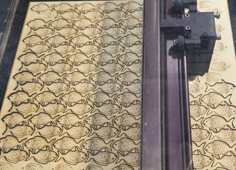
About a year ago I make a bunch of loaves and fishes for a Godly Play story at the church. I made them out of 3mm door hanger plywood that I picked up at the local craft store using a…

Apparently this new version is a lot better at math, so I tested it out with some simple calculations. Here’s how that went: This is pretty straightforward. A 3.65″ diameter is a circumference of about 11.5″, and that distance 1,750…
Use code “MAY20SALE” to get 20% off rack plans in May. This code can only be used a limited number of times, so don’t delay! Go to the purchase page here and enter the code at checkout! Consider this…
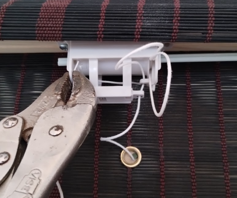
We got these blinds a couple of years ago from Amazon, and recently one of the string take-up mechanisms jammed because the string apparently came off the pulley wheel and wrapped around the shaft. I contacted customer service about how…