
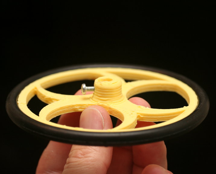
I built a framework for robot wheels a while back using OpenSCAD and used it to create a few different wheel styles. I recently decided to combine them all into one massively configurable wheel model, and add a number of new features as well. The result is an OpenSCAD file with 46 parameters that provides a limitless set of combinations and wheel designs. I call it One Wheel To Rule Them All.
It includes twelve tread patterns (all configurable in often surprising ways), eight core spoke patterns (also highly customizable), configurable support for o-rings, bands, and even optical encoder timing slots (directional and non-directional), and a lot more. Plus, I’m still adding features as I think of them.
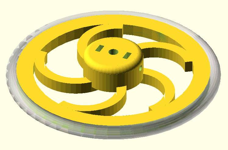
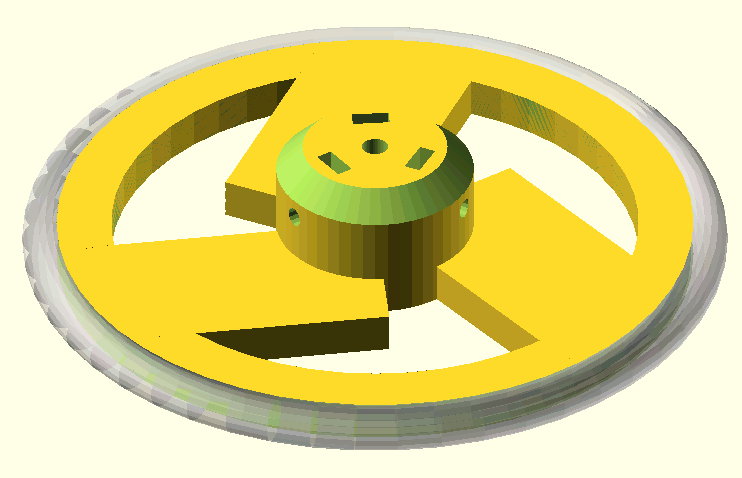
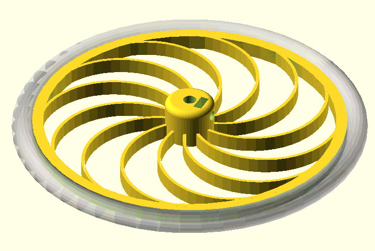
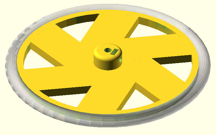
First, here are a few images of the types of the various basic elements, as well as a few variations that show the flexibility of the designs. For example, as shown in these images, the Spiral style can be used to create a variety of interesting designs that you might not think of when you think “spiral.” After the images you’ll find full details on the parameters.
It’s important to note that you can configure this wheel to such an extend that it may not be printable at home with extruded plastic printers. In these cases, services such as Shapeways could come in handy.
The source file is available at http://www.thingiverse.com/thing:21486, or on github at http://github.com/alexfranke/Highly-Configurable-Wheel.
Licensing
 |
This design is licensed under the Attribution - Non-Commercial - Share Alike license. On Thingiverse at: http://www.thingiverse.com/thing:21486 |
Tire Parameters
Often wheels are built around the tires. In this section, specify the properties of the tires you’re using, and this will define the diameter of the wheel. If you’re using o-rings, the tireCSDiameter should be the cross-section diameter of the o-ring, or if you’re using some other flat tire material (such as rubber bands), jsut specify the its thickness. If you’re not using any tire at all, set the tireCSDiameter to zero.
- wheelWidth: The width (or thickness) of the the wheel
- tireCSDiameter: Cross-sectional diameter (CS) — How thick is the tire rubber?
- tireID: Internal diameter (ID) — How wide is the inside opening?
- tireStretch: Circumferential stretch percentage (usually 1 + 0-5%) — How much to you want to stretch it to get it on?
Rim properties
The rim sits at at the outside of the spokes and supports the tires or added treads. Installed tires (such as o-rings, rubber bands, etc) are set into grooves carved out of therim, while trads are added onto it. Keep this in mind when you’re using tires — as an example, the rim height should not be smaller than the radius of o-ring tires.
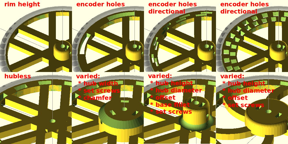
The rim also supports rotary encoder timing holes for wheel feedback. Use the padding parameters to adjust the location of those holes. See the compiler output for helpful information about the distance indicated by each timing hole. Directional timing holes will produce a second set of holes that are 90 degrees out of phase with the first. This allows you to stack sensors at the same location over the wheel instead of trying to position them along the circumference. Directional timing holes essentially double the resolution. You can also double resolution by looking for both rising and falling edges.
- rimHeight: The height of the rim portion of the wheel
- timingHoles: The number of timing holes to carve into the rim
- timingHoleInPad: The inside padding for the timing holes
- timingHoleMidPad: The middle padding if direction timing holes is selected
- timingHoleOutPad: The outside padding for the timing holes
- directional: A directional encoder renders two sets of slots, 90 deg out of phase
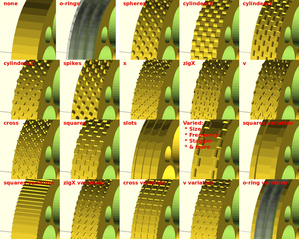
Tread Parameters
In this section, specify the properties of the tire tread you want to render. If you’re using a wheel (e.g. o-ring, rubber bands, etc), then use either the “o-rings” or “slots” settings, which will cut a groove (or grooves) in the wheel rim to fit the tires. The othertreat styles will render a tread pattern protruding out from the tire surface by the amount you specify in third part of “knobSize”.
Imagine the tire is mounted on a robot and facing straight at you. The “knobSize” parameter defines the size and shape of knobs in an [x,y,z] format, where x goes across the rim, y goes up and down along the perimeter of the wheel, and z protrudes out from the wheel toward you.
The “staggerOffset” parameter allows you to stagger knobs across the tire by an amount you specify. Set this to zero if you want all the knobs lined up along the perimeter and aligned with the edges of the rim.
“numberOfKnobs” specifies how many knobs there are across the tire, and “lineThickness” specifies how thick the lines are from “drawn” tire styles, such as “x”, “cross”, and “zigX”. You can use these pameters together in creative ways — for example to extend a single tread profile across the width of the tire, or to create a contiguous zig-zag.
Finally, “radialTreadSets” defines how many sets of treads are rendered around the wheel. Each set contains two rows in order to create the staggered effect.
Tread styles are:
-
- none: No tread is rendered
- cross: Each knob is the shape of a plus sign with the specified lineThickness
- o-rings: Grooves are cut into the rim to accept o-ring tires
- squares: Each knob is a rectangle, whose size is specified by knobSize
- spheres: Each knob is a smooth bump, whose size is specified by knobSize
- cylindersX: Each knob is a cylindrical shape running across the wheel, whose size is specified by knobSize
- cylindersY: Each knob is a cylindrical shape running along the perimiter of the wheel, whose size is specified by knobSize
- cylindersZ: Each knob is a cylindrical shape protruding from the surface of the wheel, whose size is specified by knobSize
- spikes: Each knob is a cone or spike protruding from the surface of the wheel, whose size is specified by knobSize
- slots: Grooves are cut into the rim to accept flat tires, defined by numberOfKnobs (number of grooves), the first and third numbers in knobSize to define the width of the slots and the depth, and spaceBetweenTires for the distance between the tires and also from the outside edges to the first slots.
- x: Each knob is in the shape of an “x” protruding from the surface of the wheel, whose size is specified by knobSize
- zigX: Each knob is in the shape of a zig-zag protruding from the surface of the wheel, whose size is specified by knobSize
- v: Each knob is in the shape of a “v” protruding from the surface of the wheel, whose size is specified by knobSize
- treadStyle: none, cross, o-rings, squares, spheres, cylindersX, cylindersY, cylindersZ, spikes, slots, x, zigX, v
- knobSize: The size of each knob [across wheel, along the perimeter, prodruding]
- radialTreadSets: How many sets of treads to render around the wheel (2 rows per set).
- numberOfKnobs: The number of knobs to render per row.
- staggerOffset: A distance to offset the staggered rows.
- lineThickness: The line thickness for “drawn” styles, such as “x” and “zigX”
- maxTires: For o-rings, the maximum number of tires per wheel
- spaceBetweenTires: For o-rings, the space between each tire, if there are more than one
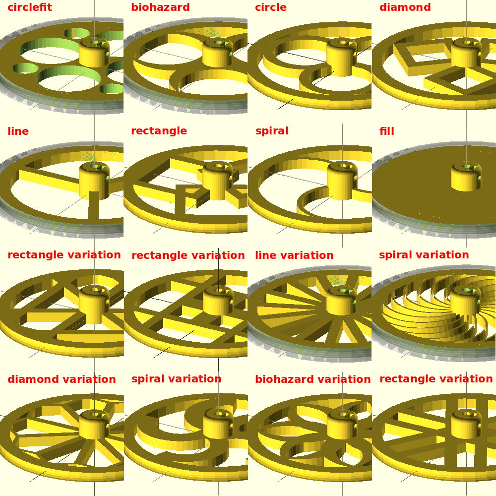
Spoke-related Parameters
This section is used to define the spoke style of the wheel. Some of the properties are only applicable to certain wheel types, and these properties can be used together in creative ways to create a wide range of tire designs.
The “proportion” property affects how some spokes are rendered. The first number is the proportion of the design from the center of the wheel to the inside of the rim, and the second number is the proportion of the width inside of the wheel. For example, to create spokes that are roughly in the shape of a “U”, you can use a “circle” style, and set the proportion to [1.5, 1.0], for cirle spokes that are 150% as long as the distance from the center to the inside of the rim, 100% as wide.
Use spokeInset to specify the inner and outer inset of the spoke area from the inner and outer faces of the wheel. You can use a negative number to make the spoke area stick out further than than the rim. The hub position will be based on the inner surface resulting from this inset.
The spoke styles are:
-
- biohazard: A biohazard logo-inspired design. Set numberOfSpokes to 3 to mimic the logo.
- circle: Spokes in a circlar or oval form, defined by spokeWidth and proportion.
- circlefit: The maximum number of circles that will fit between the center and the rim, with a set of smaller outer circles specified by outerHoleDiameter.
- diamond: Spokes in the shape of a diamond (rhombus), defined by spokeWidth and proportion.
- fill: Fills in the spoke area with a solid cylinder.
- line: Straight line spokes, like you would see on a typical wagon wheel.
- none: Leaves the spoke area empty and does not make for a very useful wheel.
- rectangle: Spokes in the shape of a rectangle, defined by spokeWidth and proportion.
- spiral: Spokes in the shape of a semicircle, defined by curvature, reverse, spokeWidth.
- spokeStyle: none, biohazard, circle, circlefit, diamond, line, rectangle, spiral, fill
- spokeInset: The [inner,outer] inset of the spoke area from the surface
- numberOfSpokes: Number of “spokes.” Set this to three if you’re doing the biohazard design
- spokeWidth: This is how wide each spoke is.
- proportion: proportion to rim, proportion of width
- curvature: For “spiral”, this is how curvey the spokes are. >0, but
- reverse: For “spiral”, setting this to “true” reverses the direction of the spirals
- outerHoleDiameter: For “circlefit”, the diameter of the outer holes, or zero for non
- concavity: Concavity distance of spoke area for [inside, outside] of wheel
Hub Parameters
These properties define the hub — or how the wheel connects to the motor. The default values for the captive nut are precise for a M3 nut and will make the nut a very tight (if not impossible) fit. I prefer this because it allows you to “melt” the nut into place with a soldering iron. However, if you don’t have a solder iron or prefer a looser fit, then just adjust the nut diameter and thickness. (M3 hardware is, by default, set to 3mm screw diameter, 5.4mm nut diameter, and 2.3mm nut thickness.) Similarly, the holes for the motor shaft and grub screw are also precise. This allows the holes to be drilled out for a more precise fit. Again, you can adjust these to suit your needs.
The hubZOffset can be used to “sink” the hub into the wheel, and it defaults to half the wheel thickness. For example, when the hubHeight is 10 and the hubZOffset is -2, then the hub will protrude 8mm from the wheel, but the shaft hole will be 10mm deep. The set screw will still be positioned in the middle of the exposed vertical height, and the fillet/chamfer will also be rendered in the correct position. This property is also useful if you want to poke a hole entirely through the wheel. (e.g. If the wheel is 6mm thick, set the hub height to 16 and the hubZOffset to -6, and you’ll get a hub that protrudes 10mm from the wheel surface with a hole that extends all the way through the wheel.)
To mount a servo motor, set includeHub to false, set shaftDiameter so that the hole will accommodate the servo horn screw and any bit that protrudes from the top of the servo horn. Then set the servoHoleDiameter to the size of your mounting hardware, and set servoHoleDistance1 and servoHoleDistance2 to the total distance between mounting holes on your servo (not the distance from the center). These sets of mounting holes will be rendered at 90 degree angles from one another. If you only want one set of holes, set one of the values to zero. Adjust the angle of all the holes to avoid openings in your wheel design if necessary using servoArmRotation.
Use innerCircleDiameter to specify a solid inner circle to use as a base for the hub. This can be useful if you need a a solid surface for servo mounting hardware or for the base hub fillet/chamfer.
Use outerNutTrap to create a nut or bolt head trap on the outside (bottom) of the hub area. Used in conjunction with shaftDiameter and false for includeHub, this will create a wheel that can drive a bolt much like the large gear on Wade’s Extruder. (This feature is inspired by that design.)
Use servoNutTrap to create nut traps for bolts used to mount the wheel onto servo arms. This feature was suggested by AUGuru.
- includeHub: Set to false to remove the hub and only include the shaft diameter hole.
- hubDiameter: The diameter of the hub portion of the wheel
- hubHeight: The total height of the hub
- hubZOffset: The Z position of the hub, negative numbers from the surface of the wheel
- shaftDiameter: The diameter of the motor shaft
- innerCircleDiameter: The diameter of the solid inner circle under the hub, or zero for none.
- setScrewCount: The number of set screws/nuts to render, spaced evenly around the shaft
- setScrewDiameter: The diameter of the set screw. 3 is the default for an M3 screw.
- setScrewNutDiameter: The “diameter” of the captive nut, from flat to flat (the “in-diameter”)
- setScrewNutThickness: The thickness of the captive nut
- baseFilletRadius: The radius of the fillet (rounded part) between the hub and wheel.
- topFilletRadius: The radius of the fillet (rounded part) at the top of the hub.
- chamferOnly: Set to true to use chamfers (straight 45-degree angles) instead of fillets.
- servoHoleDiameter: The diameter of servo arm hounting holes, or zero if no holes
- servoHoleDistance1: Distance across servo horn from hole to hole (0 to ignore)
- servoHoleDistance2: Distance across servo horn from hole to hole, rotated 90 degrees (0 to ignore)
- servoArmRotation: The total rotation of all servo holes
- servoNutTrap: Size [indiameter, depth] of servo arm captive nut, or 0 (any) for none.
- outerNutTrap: Size [indiameter, depth] of a captive nut, or 0 (any) for none.
Quality Parameters
- $fn: Default quality for most circle parts.
[…] theFrankes.com · Highly Configurable Wheel One Wheel To Rule Them All. […]
Great design. Useful for lots of things and well documented.
One little addition I did was to support motors with two flats like some of the cheap steppers. I added a variable shaftDoubleFlat (true/false) and then just added
if (shaftDoubleFlat) {
translate([-((boreDiameter-shaftFlatDiameter+1)/2 + (boreDiameter/2)
– (boreDiameter – shaftFlatDiameter)),0,0])
cube( [boreDiameter-shaftFlatDiameter+1,boreDiameter,height+2], center=true );
}
to the difference in Remove the bore
[…] the simple hook, this is far from trivial to design yourself and I was again very pleased to find this guy did an excellent job at providing a hugely configurable OpenSCAD […]
I modified your design to accommodate an axle with a screw directly in the end of the axle, screwing in toward the vehicle body. Further I needed body clearance requiring the InnerCircle, below the hub, to be extended beyond the wheel rim. The hub proper, holding the axle, is actually now outside of the rim width!
Secondly, for the axle screw to grip the wheel to the end of the axle, I added a “screw plate” at the base of the hub, with a screw body hole through it.
I am happy to upload this modified design, if you can point to a place, or email for it!
Thanks!!!
[…] big thank you to this guy, as I’ve used his OpenSCAD (have you noticed yet what a big fan I am !? ) script to generate […]
great little file and high level of thanks to you all. I have just found it and upon loading into Openscad it sends a warning..
DEPRECATED: The assign() module will be removed in future releases. Use a regular assignment instead.
Thanks again