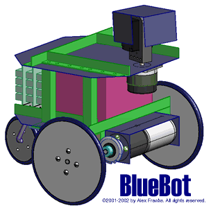
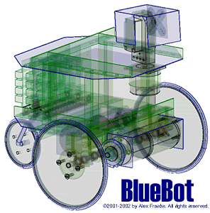
NOTE: Each picture on this page has its own scale.BlueBot is a platform for autonomous robot experimentation, engineered around a specific set of motors. It’s in itself an experiment in mixing easy-to-find components and custom components, with the end goal being a well-engineered, compact, flexible and expandible platform for experimentation and development. It’s a learning tool in development, construction and customization. Some of the requirements were predefined, while others were dictated by available tools and parts.
Drive Motors
It all started with four Globe motors I picked up on Ebay. These particular motors are apparently used for autonomous robotics competitions, so I thought they’d be perfect for this application.
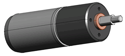
Two of these drive gearmotors are fastened under the chasis, each driving one side wheel. To keep BlueBot compact, I decided to offset these motors from the center axes of the wheel axels. This has a couple of benefits. First, it’s easier to control the wheel-to-motor speed ratio. Second, I avoid the temptation of mounting the wheels directly onto the motor shafts. Although these motors could probably handle the weight of the robot with no problem, I though it best to separate the two.
Chasis
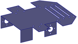
The chasis is constructed from sheet metal and requires a few cuts, a few bends and a bunch of holes for mounting. My goal in designing the chasis was to make it compact and as easy as possible to produce. I started off with a flat piece, and made a few cuts and bends to contain the motors. The motors are housed underneath the chasis in the two narrower sections. You can see one set of mounting holes on each side of the chasis. Because the motors hang under the chasis, a single bend of the sheet metal is not strong enough to hold them in place. Therefore, a strap is added to the non-mounted end of the motor to hold it steady. (Mounting holes for the strap are not shown.) The long slots at the back of the chasis allow for circuitry venting. The back corners were cut diagonal to match the general octagonal shape I ended up with.
Drive
I decided on interchangable sprockets with a #25 roller chain for drive. Here’s a couple of bottom views (top=front). The chain is not shown in their views, and the sprockets pictured are not notched all the way around, but you can get the general idea of how they are aligned.
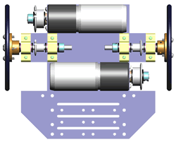
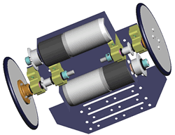
Here you can see the two motors mounted onto the sheet metal chasis. The top (front) motor controls the wheel shown on the left (though it’s actually the right wheel). You can also see a few of the custom parts from this view. The first is the wheel itself, which was designed around easy-to-find vacuum cleaner o-rings. The next custom part is the wheel hub, and the final custom part is the pillow block. The four (yellow-gold) pillow blocks used to hold the axles in place. The “wings” that support the wheels are strengthened from above (more later). There is space between the two axles to house the encoder electronics. The holes at the bottom (rear) of the chasis are used to fasten circuit boards and provide venting. An enclosed motor driver circuit (not shown) and a fan (if necessary, not shown) are also mounted beneath the chasis at the rear of the bot. If a fan is used, it is pointed down, bringing cool air through the PCBs above the chasis and the heat sinks of the motor driver board below the chasis. I suppose you could point the fan up if you want BlueBot to vaccuum, but you’ll end up with dirty electronics.

Drive Wheels
I originally wanted to make the wheels with the stack of AOL CDs I’ve collected over time. The ~4 3/4″ diameter of the CDs would give the bot more speed and the ability get over simple household obsticles. (The gear motors offer a pretty good torque rating.) For tread, I considered a number of easy-to-find products, such as rubber bands, balloons, o-rings, and even the plastic tubing you use in fish tanks. O-rings look the best, and I figured they’d be easy to find and cheap. Unfortunately o-rings of this size are neither easy to find nor cheap ($6 each locally, or I could buy a lot of 20 online and pay shipping, too).
I did, however, find ~4″ diameter o-rings in the vacuum cleaner section of the hardware store, and since kludging the CD wheel solution was giving me problems, I went back to the drawing board and designed a custom wheel, which can be cut from 1/4″ plastic. I added holes for the axle and for mounting, and a groove to hold the vacuum cleaner o-rings into place.
The hubs are another custom part and serve to fasten each wheel to its own axle. Only the set screw holes are threaded, and since the threads need to be strong enough to hold the wheels to their axles, I thought this should be a metal part. The following images show an enlargement of the hub, and the wheel assembly.

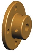
Wheel Mount
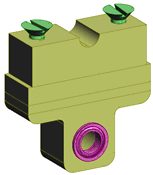
The drive wheels are held in place with four custom bearing housings. The body of each housing is broken into four secions: the base (shown at the top of the image), the top (shown at the bottom) and two shims. The shims allow the user to adjust the distance from the chasis to the axle in four 0.1″ increments, thereby assuring a resonably tight chain fit. The base is slightly narrower than the other parts to allow it to fit snugly between two easy-to-find L-shaped aluminim bars. I use sections of these L-shaped bars to reinforce chasis, and for other porposes as well. The half-circle between the mounting screws allows space for wires to be run.
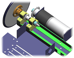
The following image shows how the wheel (grey), hub (brass), pillow blocks (yellow), L-shaped strengthening bars (green), motor and sprockets fit on the chasis (blue). Note the notch cut out of the opposite end of one of the green structural supports (lower right-hand corner of the image). This notch allows extra space for the chain for the wheel that is not shown. There’s a notch for the other wheel, too, but it’s mostly hidden by the wheel sprocket. I chose sprockets, by the way, because there are a few online sources for inexpensive surplus sprockets. Gears would have provided a little less flexibility at a higher cost.
Caster
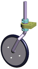
BlueBot’s back wheel has the same mounting holes as the front wheel but is sized to fit smaller o-rings. There’s a 30-degree bend in the axle to allow it to swivel as the robot turns. The axle is held in place with a couple of shaft collars on either side of a mounting block, allowing the height to be adjusted up and down as needed. The mounting block is fastened to the back of the chasis.
Deck 1
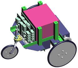
In this configuration, BlueBot’s motors are powered by a standard sized 7AH sealed lead acid (SLA) battery, positioned so that the bot’s center of gravity is low and adequately behind the front axles. There is space behind the SLA battery for 3 full-sized circuit boards (many are smaller), and space in front of it for sensor circuitry. You can see the additional L-shaped structural support (green) in this image as well. The tall square spacers support Deck 2.
Head & Deck 2
The head mechanism is built around a standard hobby servo and a 1.8-degree stepper motor that I salvaged from an old HP ScanJet scanner. It’s pictured here attached to Deck 2. The stepper motor is mounted below Deck 2 and provides panning for the head. Some bots simply turn the wheels to pan, but I believe this is the more ideal solution because the wheels should only be concerned with moving the robot. This also allows the robot, for example, to scan side to side while driving.
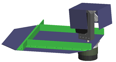
The hobby servo motor (black), which provides the tilt, is mounted to the shaft of the stepper motor with a custom plastic piece (dark gray). You can just see how the corners of the pice are rounded to allow full tilt of the head without interfering with the sheet metal shell.
A sensor or camera (not shown) is mounted behind the front of the head (the face) by drilling the appropriate mounting holes. Supporting circuitry resides behind the head so as not to add unnecessary weight to the head.
The Result
This is what I ended up with. (Same pictures as at the top of this page.)


