I’m rolling my own home security system for pennies on the dollar (and lots and lots of time, but this kind of stuff is fun to me). Here’s what I ended up with for the kitchen. It controls three distinct lighting zones and three entry points (two doors and one window). It has its own captive portal for network/LED/sensor configuration (using Autoconnect) and it’s fully connected. So far it’s testing out pretty well. Here are the notable parts:
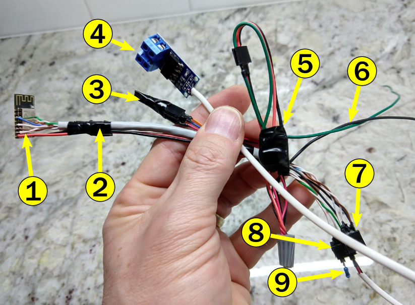
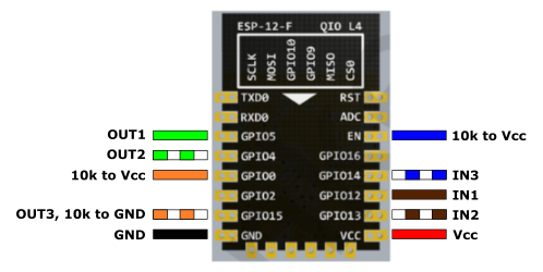
- ESP-12F ($1.09 from Aliexpress). This is the brain — the venerable ESP8266 module, with some custom code to control the lights, sensors, and communications. I used pins 5, 4, and 15 (with a 10K to ground) as PWM outputs, and pins 12, 13, and 14 as inputs. I broke out pins EN and 0, as well as VCC and GND and soldered up the wires so I could re-insert it into the programmer in case the OTA updates failed.
- Cat-5E network cable (free, on hand). I use this stuff a lot. I used all eight wires in the cable, plus a couple more for VCC and GND.
- Resistor Header (a couple cents). I broke out EN and pin 0 so I could place 10K resistors and remove them again if necessary to program.
- Dual MOSFET Trigger ($0.84 at Aliexpress). This triggers with 3.3V and drives up to 36V, 400W — plenty for each of my three 12V LED lighting zones. There’s one of these per output channel. The one on pin 15 also contains a 10K resister to ground, which is necessary for normal operation.
- Mini DC Step-down Buck Converter, 3A ($0.50 on eBay). This takes the power from the 12V LED power supply and efficiently converts it down to the ~3.3V operating voltage of the ESP-12F. I originally planned on using a linear regulator thinking that this might cause some interference with the ESP, but that turned out to not be a problem. (The AMS 1117 regulator would have probably run hot, but not too hot.)
- Power (free, on hand). This connects to the 12V power supply. I used green for 12V because that’s what I had on hand.
- Input Sensor Header (free, on hand). This breaks out the three input pins in a 2×3 header, once side of which is all GND.
- Output Header (free, on hand). This breaks out the three output pins in a 2×3 header, once side of which is all GND.
- Removable 10K resistor (pennies). The third output channel MOSFET driver has this resistor soldered on, but it basically takes pin 15 low, which is required for normal operation.
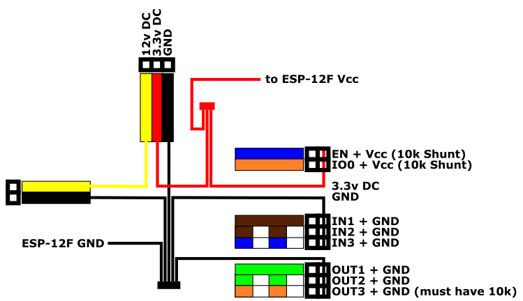
Here’s how I planned out the wiring and headers: