A couple days ago, after putting off the project for decades (you know, kids and all), I finally dug out the old Atari 800 I had as a kid. The 800 fired up after a bit of cleaning but I’m pretty sure I need to replace some caps because the power seems pretty unstable. The 810’s head stepper worked, but not the spindle motor. Here’s how I diagnosed and repaired the drive motor.
I got this machine in about 1982, by the way. I’m a software guy and merely a hardware tinkerer, so this was a learning experience as I chased down problems that will likely seem obvious to those more experienced… I probably also made some mistakes along the way, so feel free to point those out so other hobbyists don’t make the same mistakes.
Repairing the Drive Motor
When powered on, the drive head moved back and forth but the disk did not spin up as I remember it used to. The belt looked good and the motor turned just fine by hand but the spindle rattled quite a bit. I immediately recognized and remembered this from the 80’s. At some point after that noise started, the drive simply stopped spinning altogether, and it’s been sitting in random closets and attics ever since.
I found some schematics online and printed them out (https://archive.org/details/Atari810DiskDriveFieldServiceManualRev1/page/n148/mode/1up). Revision 1 matched my drive. Importantly, I did *not* find this forum or the diagnostic troubleshooting flowchart that’s been posted here and there, and that would have certainly saved me some time if I did.
The Spindle Rattle
- The motor spun freely (but with a rattle) and belt looked good. The drive itself appears to be a Wang MPI 51, and I found the manual for that online at https://www.wang2200.org/docs/external/MPI_51-52_FlexibleDiskDriveProductManual.729-1114.5-82.pdf
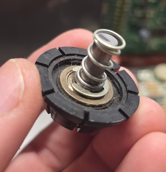
- The rattle was coming from the cone assembly at the top, so I followed the instructions in the manual (section 5.4.6) to disassembly it. The bearing (an NMB SSR-4ZZ) seemed fine, but I put in a drop of sewing machine oil anyway, just in case. I put that assembly back together and the rattle was surprisingly gone. I don’t think it was the bearing that was making the noise, but possibly that something had gone wonky with the spring or the assembly, or something got in there… or maybe it was the bearing and it just worked itself out, or the oil was just want it needed.
The Motor and PCB
- I tested the resistance on pins 2 & 3 of the motor header (red and blue wires) to see if it was shorted, and it was not.
- I gave the motor 12V directly and it spun.
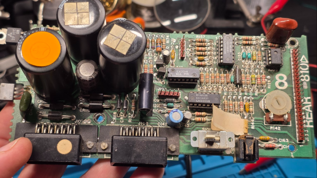
- I tested the 5V (7805) and 12V (rectifier) rails and they were fine.
- I verified continuity between
- Rear board rectifier and side board pin 20 (12V)
- Rear board R145 and side board pin 9 (motor control signal)
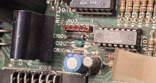
- Rear board R145 and A107 (CA3086) pin 11, where the signal enters the transistor array
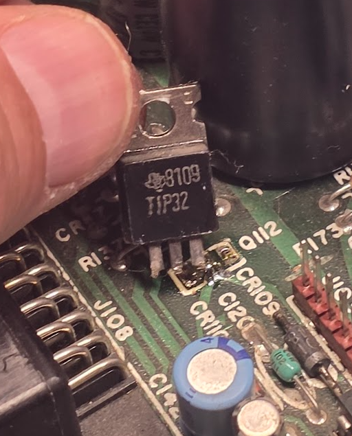
- Rear board A107 (CA3086) pin 1, where the control signal exits and the base of Q112 (TIP32)
- Rear board Q112 emitter to side board connector pin 21 (12V motor supply current)
- Rear board Q112 collector to drive motor header pin 2
- Side board 6532 pin 9 (PA1) and rear board connector pin 9 (motor control signal)
- I checked the voltage during power-on at
- Side board connector pin 21 = 12V, as expected
- Side board connector pin 9 (motor control signal) was 2.2V for about 6 seconds, then down to zero. The control logic was working but it should be 5V.
- Side board A104 (6532) pin 20 = 5V, as expected
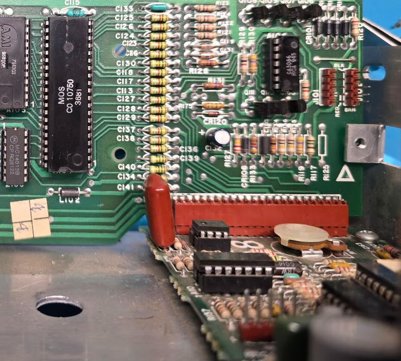
The Control Logic and Power Transistor
- I removed side board A104 (6532), bent leg 9 out and re-inserted it to test pin 9 along, and it read 5V for several seconds after start-up. re-inserted it with the leg back in place because the problem appeared to be downstream of this.
- I removed rear board chip A107 (CA3086) and tested each transistor with the multimeter in diode mode. Q5 didn’t test like the others, so I thought that one might be dead.
- I noticed that A110 is also a CA3086 so I took that out and tested it. Q5 behaved the same way, so it’s apparently wired differently.
- The only thing left was the main drive transistor Q112. With a 1k resistor, I tried to pull the base to ground while the drive was on, and the motor would not start. The voltage at the base measured about 3V consistently during the start-up process, the emitter measured 12V and the collector measured 0V. The transistor had apparently failed, so I replaced it and the drive spins as expected now.